Comptia Security+.
This is the third article in my VLan series. If you dont know what Vlans are you may want to check out Vlans; the basics and Configuring Vlans first.
This is the third article in my VLan series. If you dont know what Vlans are you may want to check out Vlans; the basics and Configuring Vlans first.
Using IP phones is a little different as the phones contain a small in built switch. Your PC connects to the IP phones inbuilt switch using an Ethernet cable. The phone then connects to the Cisco switch as normal. Traffic from your PC routes to the main switch through the phone.
If you click on the phone in Packet Tracer and zoom in you will see the two Ethernet connections. One port for the cable to the PC and the other port is for the connection between the phones switch and the main Cisco switch.
Phones use two VLans; one for data as normal and the other for voice. Separating the Vlans is helpful for a Quality of Services (QoS) perspective and also for security. With QoS the voice Vlan can be prioritized over data because a phone will become unusable if the voice traffic is patchy or muddled up.
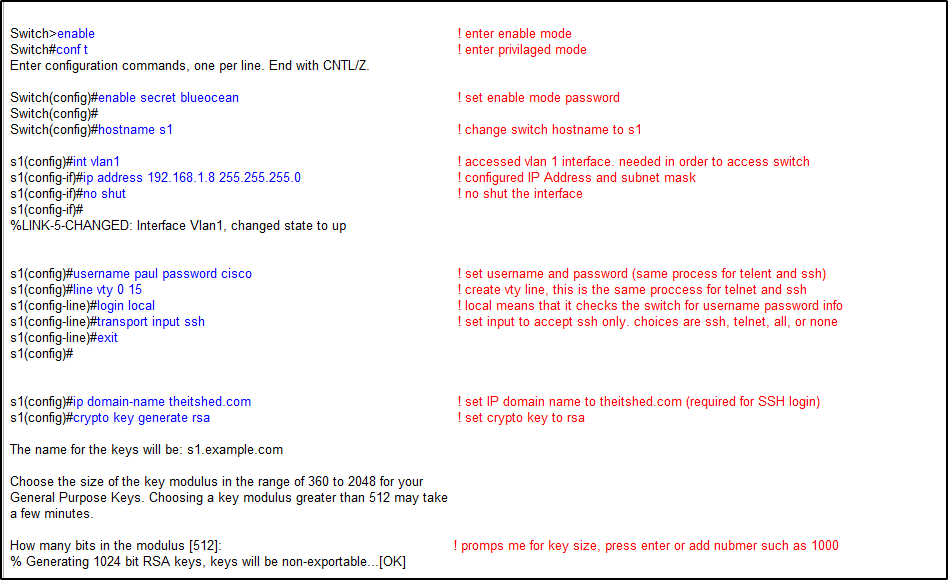
Creating VLans for voice is not much different than creating regular Vlans. In this example I am going to create the Vlan the short way as I showed in Configuring Vlans. Even though the connection carries two Vlans it will be an access connection and not a trunk as you might have thought.
Notice that the Vlans did not exist before hand as we are using the short way to create them. The switch notices this and automatically creates them for us (highlighted in blue). Also note that you can create the data and the voice Vlans on any of the Vlans, it doesn’t necessarily have to be on Vlan 2 and 3.
Now lets verify that we configured it properly. Use the command;
show interface fastethernet 0/1 switchport
Notice that the Administrative mode is static access because we manually set it. Notice also that we have two Vlans; the data Vlan; Access mode Vlan 2 and the voice Vlan; Vlan 3.
You will notice that the Operational Mode is down. That potentially be for any number of reasons but in this case it is because the IP phone is not powered up.
Some devices on Packet Tracer such as routers have a power button that you need to switch on before using the device. The IP phone needs to be powered up to work but does not have a power button.
You will need to drag the power supply located on the bottom right to the power connection on the bottom left of the phone.
Once power supply is connect the phone switches on.
Now if we run the command again;
show interface FastEthernet 0/1 switchport you will find that Operational Mode is now Static Access because the Phone has been powered up
So there we have it, a quick article showing how to configure data and voice Vlans for IP Phones. There is not much to it really, just make sure you use separate Vlans and use the switchport voice vlan [number] command.
Comptia Security+.
Cisco CCNA.

Diploma Information Technology.